Transforming Energy for America
Engineering
At VTC, our outstanding engineering is supported by an expert team of highly qualified engineers.
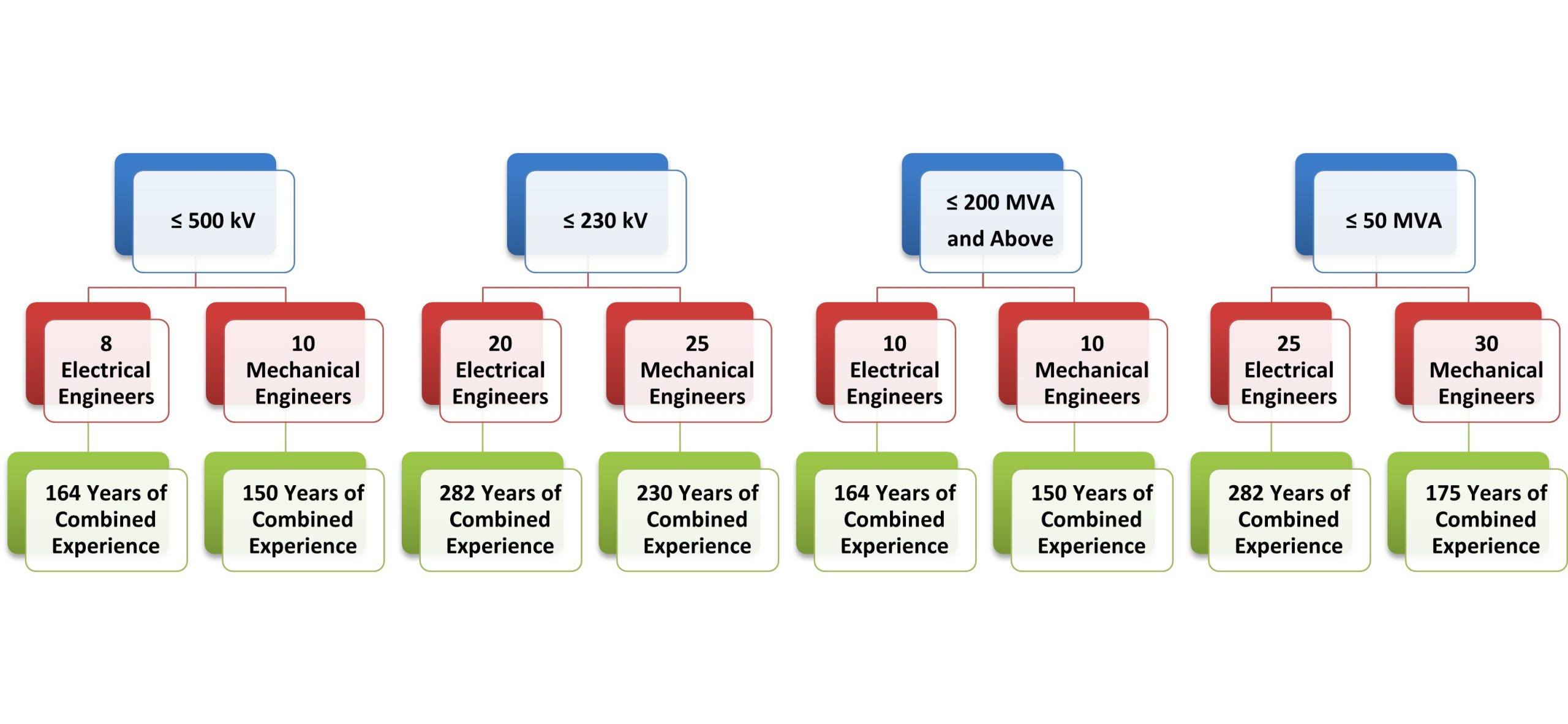
VTC’s team of engineers has a combined experience of over 150 years in 500 kV design class and close to 300 years in 230 kV and below class.

Click on the images below to meet member of our talented team of engineers.
Rakesh Rathi
Amitabh Sarkar
John K John
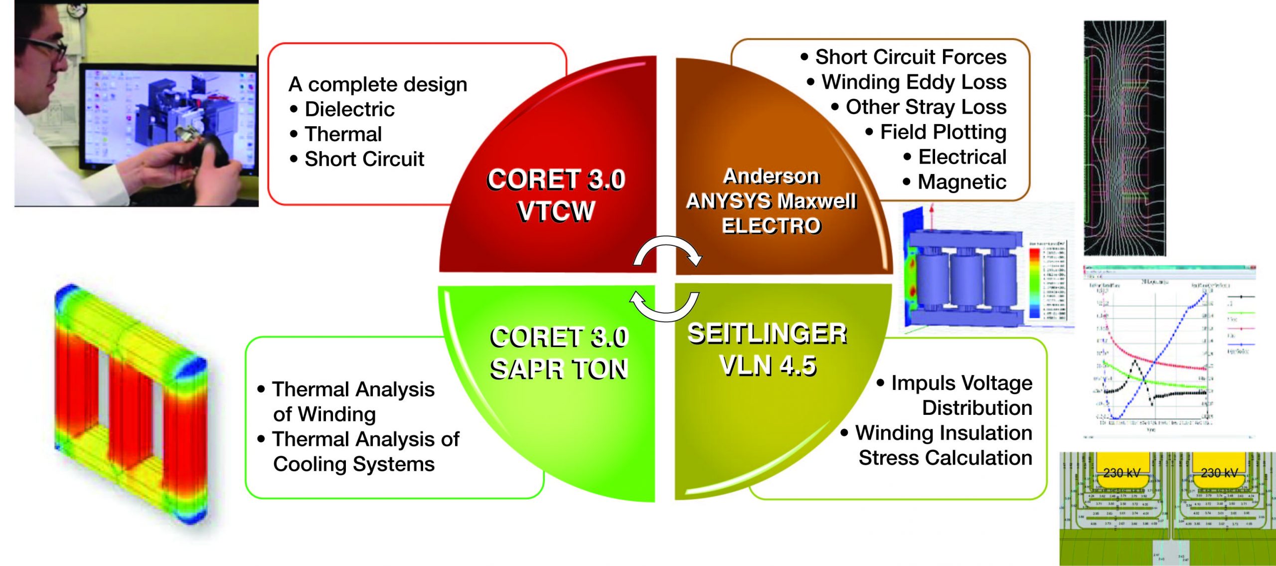
Highly qualified engineers require outstanding tools – VTC has the most sophisticated and proven software tools and simulators for electrical design. We use CORET for our main electrical design and further fine tune the design using various state-of-the-art digital simulators.

A glimpse of CORET 3 and Seitlinger digital simulators – both tools are handcrafted over 30 years.
CORET 3.0 (Developed by EFACEC) - Main program used by the Design department that allows to perform all the calculations build a transformer. (It calculates short-circuits, impedances, transients, currents,thermal heating, etc.) - in use since early 70's.
- Calculation software's embedded in Coret 3
Reluctance Network Medthod (RNM) - leakage flux analysis - LiFoCa - 2-D Modeling (Method of images)
- Glaninger - program for high frequency analysis
- Shunt - Program for thickness calculation of the different magnetic shields of the tank and support beams, and gives information for tap transposition placement
- Selfar - Calculates the coil air reactance
Seitlinger Power Engineering (RLC Transient Analysis Tool)
- CAP - Calculates the capacitances of windings in core type
- TRANEM - Calculates the wave shape of voltages, currents, and magnetic
- TATAB - Provides the possibility to search for maximum voltage stresses
- MSFT - Calculates the magnetic stray field in a core form transformer, and based on the calculated stray flux densitites, determines eddy current losses and short circuit forces for various load cases
- CDTW - Calculates the current distribution in our core type transformer windings
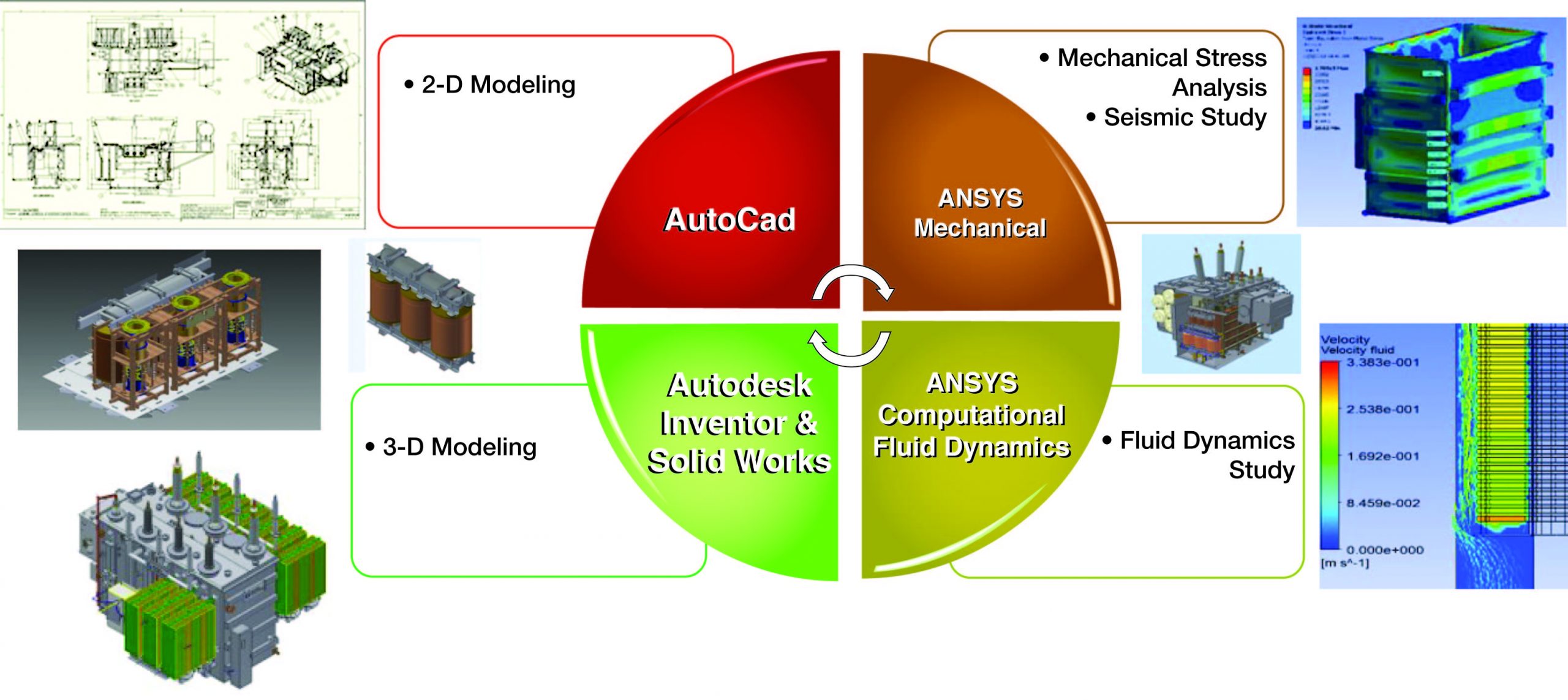
At VTC, we use state-of-the-art mechanical tools with full automation capability to eliminate design errors.


Conceptual Design
Step 1

Handshake Agreement
Step 2

Detailed Designs
Step 3

Design Buildable
Step 4

Manufacturing
Step 5
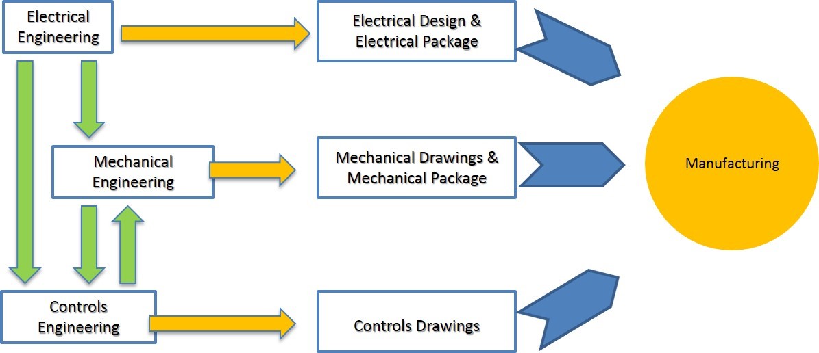
We employ an engineering process that ensures perfect coordination between the various groups – electrical, mechanical, controls, and manufacturing.
Our engineers utilize a five-step process to ensure optimum design. Complete compliancy in every step of the process is required for flawless engineering. It begins with the supervisor signing off on the conceptual design, followed by a handshake agreement between the electrical, mechanical, and controls groups. Each group develops detailed design plans and meet with the manufacturing technicians to solidify the design. The design is presented to the shop floor supervisors and becomes official.

Every unit is custom designed based on customer specifications and requirements using our internally-designed programs. After the initial design, safety factors are added to account for manufacturing tolerances and to minimize the risk of failures. Our added safety factors are based on over 50 years of experience.
Designs are checked using sophisticated analytical simulations to identify stress concentrations.
Designs are fine-tuned to distribute these stresses to further minimize the risks.
In addition, over 20,000 archived designs are leveraged to benchmark new designs.
We believe in sharing our knowledge and expertise to educate and guide our customers in the right direction.
Designs based on Westinghouse/GE fundamental technology

Every unit custom designed based on customer specification and requirements using proprietary proven design programs developed over 50 years

Safety factors developed based on 45 years of experience added to the designs to account for manufacturing tolerances and increased reliability

Designs checked using digital simulation programs to identify stress concentrations

Design tweaked to redistribute stresses to minimize risks

Leverage over 20,000 archived to designs from the VTC archives to benchmark designs

